ELECTRICAL MACHINE TRAINER

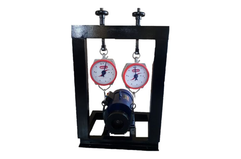
Salient Features:
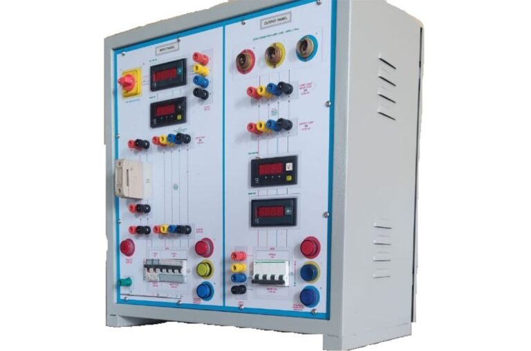
- Facilitates easy & safe wiring by students due to 4 mm sturdy shrouded banana patch Cords.
- Provided Short circuit and overload protection using Fuse/ MCB/CB/OL thermal relay.
- Included Earth socket on control Trainer from student’s safety point of view.
- The components fitted on the Panel are labelled with the name of the component.
- All components are connected with internal wiring and provision for external wiring using shockproof patch cords.
- Provided set of Instructor Guide & Student Workbook.
- MS/ABS molded plastic sturdy enclosure & rust-free powder coated control panel.
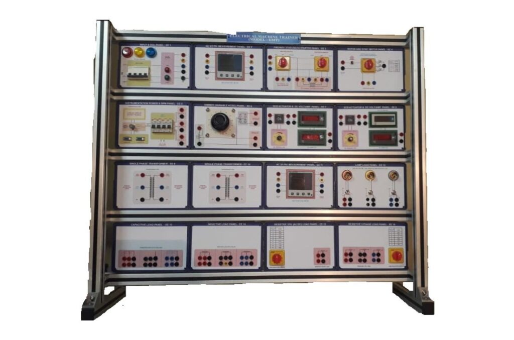
- Modular Panel with Colorful overlays showing circuit diagram & its connection tag numbers for easy understanding, connections & servicing by swapping at site.
- MS/Aluminum profile sturdy flat panel (table top) system, carrying various high voltage components housed in plastic enclosures (panel) to minimize shock possibility.
- Modular, multi machine/motor, multi experiment training system useful for visualizing & demonstrating the construction and functioning of different types of (Single phase and three phase) DC and AC Machines.
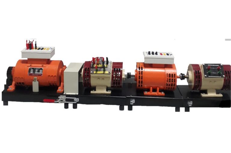
- Trunnion mounted DC Integrated machine is used as Dynamometer for loading other machines (Motors / generators both), with facility to measure shaft power using electronic torque / speed measurement.
- All machines are mounted on finely painted sturdy base frame with easy machine interchangeability, Use of screw less gear coupling/Love –Joy coupling facilitates.
Control Panel Technical Specifications:
EE1 – Three phase Power Supply panel:
- MCB 4 pole, 4 Amp, 415V AC, 50Hz.
- RYB power input Indicator (22 mm) x 3 Nos.
- Volt meter 415V AC ( 72x72mm)
EE2 – Three Phase DOL Starter panel:
- Contactor 9 Amp. 415V, 50 Hz, 3 Pole, 1 NO.
- Contactor Coil: 230V, 11VA.
- Bimetallic over load thermal Relay.
- Relay Range 1.4A – 2.3A. (Set: 2.3 Amp.)
- Start-Stop Push Button Switch.
- DOL ON Red Indicator (22mm
EE3 A/B/C – Multi-function Bi-directional Power Measurement Panel (2 nos.):
- Digital Bi-directional Multi-function meter (96X96mm).
- 3 Phase 3/4 wire, Voltage line to line & line to neutral.
- Measurement of 415V, 3 ph. & 230V, 1 ph. parameters.
- Measures V, I, Hz, PF, KW, KVA, KVAr, Energy in KWh.
- Current for all 3 ph. up to 5A. (Inbuilt CT 5A:5A x 3 Nos.)
- LCD/LED display, Reverse Power Indication.
- Supply 230VAC, 45-65Hz, 5W
- Optionally PC interface with RS485 (Power Analyzer)
EE4 – FWD/REV, Manual Star- Delta Starter panel:
- Three Ph. ON-OFF-ON with FWD/REV, 3 pole 3 way switch with center OFF, 6A/440V.
- Star/Delta switch 3 pole, 3 way with Centre OFF, 6A/440V.
- Starter ON & Power ON Red Indicator (22 mm each)
EE5 – ON OFF ON, FWD/REV Panel:
- Three Ph. ON-OFF-ON with FWD/REV, 3 pole 3 way switch with Centre OFF, 6A/440V.
- Power ON Red Indicator (22 mm)
EE6 – Rotor resistance Starter Panel:
- Selector switch, 3 pole, 7 Way. 6A/440 V.
- Rotor resistors of 30E/5A with 4 taps of 15E, 20E, 25E, 30E x 3 nos.
- DC Rotor excitation over current circuit breaker (3 Amp)
EE7 – Single phase Power Supply Panel:
- MCB 230V AC, 50Hz.1 pole/6A(3 Nos.) 1 pole/10A(1 No.)
- Output Terminals: 230V, 6 Amp.(3 Nos.) & 10 Amp.(1No)
- Red Power Indicator (22 mm), Lamp Holder.
- 8A push button switch (Simulate as centrifugal switch) & Resistor 30E/400W. (Provide if Single ph. Ind. Motor supply)
EE8 A/B/C – SCR Based DC Variable Power Supply (3 nos.)
- 230V AC Input, Output 0 to 195V DC, 5 Amp.
- Full bridge SCR based, Cosine firing with linear charateristics.
for Armature, motor field & Alternator/generator field.
EE9 – Signal conditioning Cum Display panel:
- Red Power Indicator (22 mm)
- Multi channel Digital RPM & Torque Display.
- Supports Sensor signal conditioning circuit for Speed, Torque in kg. to give output 0-2.5V DC (FS)
EE10 – DC Voltmeter & Ammeter panel:
- Voltmeter: 0 to 300V DC (72x72mm)
- Ammeter: 0 to 1A DC (72x72mm)
- Polarity protection diode.
- Circuit Breaker for over load protection.
- Field failure relay to control Armature.
EE11 A/B – DC Voltmeter & Ammeter panel (2 nos.):
- Voltmeter; 0 to 300V DC (72x72mm)
- Ammeter: 0 to 5A DC (72x72mm)
- Polarity protection diode.
- Circuit Breaker for over load protection.
EE12 – Variable AC/DC Power Supply Panel:
- 230V AC Input, 0 to 270V AC, 3Amp Output.
- Diode Bridge AC to DC, 0 to 260V DC, 3Amp. Output
- Full bridge Diode based.
EE13 – Single Phase AC/DC Resistive(R) Load Panel:
- Selector switch, 2 pole, 7 Way. 10A/440 V.
- Resistors 750E-600E-300E-212E-162E-100E-OFF. 400W / 7 Steps.
- Separate 60E tap for DC series Gen. (if DC Series Gen. Supply)
EE14 – Three Phase Resistive(R) Load Panel:
- Selector switch, 3 phase, 3 pole, 7 Way, 10A/440 V.
- Resistors 10K-5K-3.5K-2.5K-2K-1.5K-OFF/200W, 7 Steps.
EE15 – Inductive (L) Load Panel:
- Selector switch, 3 phase, 3 pole, 7 Way. 10A/440 V.
- Inductors: 0.15H-0.3H-0.45H-0.6H-0.75H-1.5H-3H/400 mA, 7 Steps.
EE16 – Capacitive (C) Load Panel:
- Selector switch, 1 Ph/3 phase, 3 pole, 7 Way. 10A/440 V.
Capacitive load =1mf-2mf-2.5mf-4mf-5mf-6mf-OFF, 7 Steps.
EE17 – Synchronizing/Paralleling Panel (Optional):
- Synchroscope with LED Indications.
- Three Lamps for Lamp Method experiment.
- Synchronizing Switch, Synchroscope ON-OFF switch.
Accessories :
Patch Cord,
Manual,
Dust Cover.
PC Interface & Software for data Acquisition (Optional):
- Data Acquisition using Modbus Serial RTU.
- Data Acquisition from Analog interface unit.
- Speed, torque,
- Voltages, currents,
- Frequency,
- Operating efficiency,
- Active power
- Reactive power
- Power factor,
- Calculated torque and slip etc.
3. App has facility to monitor online data as DPM as well as Charts.
- Also can save data in PDF or Excel data as per student identification (Roll no., Name) also charts can be saved as Image file.
- Has facility to copy data to Removable device
- Application based Dual Arm® Cortex®-A72 microprocessor subsystem @ 2GHz with 7” LCD HDMI device
- USB /Serial interface, keyboard mouse.
Motor, Generator & Alternator Technical Specifications:-
Machine No. 1 – DC Integrated Machine – Trunnion mount, Dynamo type with torque & speed sensors.
Note: Machine Sr. No. 1 is Compulsory & following other machines are optional.
Volt: 180V Arm. & Field, HP: 0.5HP /2 Pole RPM: 1500RPM, Terminals: 6
Rotor: Standard commutator / brush arrangement with laminated stack, brought out on 2 terminals
Stator: Separately excited field winding with laminated solid yoke 2 pole and series winding brought out on 4 terminals.
Experiments List: I) Motors: Speed torque curves of a) Shunt motor, b) DC series motor, c) Separately excited DC motor d) DC compound motor (Cumulative & Differential)
II) Generator (Needs to be driven): V-I & Efficiency curves for –
a) DC Shunt generator b) DC series generator c) DC separately excited generator d) DC compound generator.
IV) Efficiency: All above type DC m/c.
Winding Temp: Embedded Thermistor brought out on 2 eyelets mounted on terminal box for monitoring winding temperature.
Frame: 90, Shaft dia: 19 mm,
Mounting: Chassis mounted with easily swappable gear coupling. Weight Net: 45 Kg., Gross: 65 Kg.
Machine No. 2 – DC Motor/Generator (Optional with Above Machine No .1)
Volt: 180V Arm. & Field, HP: 0.5HP /2 Pole RPM: 1500RPM, Terminals: 6
Rotor: Standard commutator / brush arrangement with laminated stack, brought out on 2 terminals.
Stator: Separately excited field winding with laminated solid yoke 2 pole and series winding brought out on 4 terminals.
Experiments List: I) Motors: Speed torque curves of –
- a) Shunt motor, b) DC series motor, c) Separately excited DC motor d) DC compound motor (Cumulative & Differential)
- II) Generator: V-I & Efficiency curves for a) DC Shunt generator
- b) DC series generator c) DC separately excited generator
- d) DC compound generator.
- IV) Efficiency: All above DC m/c. (V, VI, VII) ?
- V) Swin burn’s test: Measurement of NO load losses to determine efficiency of DC shunt motor.
- VI) Hopkinson’s test: Back to back test on two identical DC shunt m/cs. (Needs 2 nos. of DC m/c to be coupled to each other)
Winding Temp: Embedded Thermistor brought out on 2 eyelets mounted on terminal box for monitoring winding temperature.
Frame: 90, Shaft dia: 19 mm, Mounting: Chassis mounted with easily swappable gear coupling. Weight Net: 38 Kg., Gross: 57 Kg.
Machine No. 3 – Single phase AC Cap. Start & Cap. Run Induction Motor. (Optional with Above Machine No .1)
Volt: 230VAC, 50Hz, HP: 0.5HP /4 Pole RPM: 1460, Terminals: 10
Rotor: Die-cast Squirrel cage.
Stator: Two windings brought out on 4 terminals for main & auxiliary these will be used to configure different motors split phase, CSCR CSIR.
Experiments List: Speed torque curves & Efficiency of –
- a) Split phase ind. motor, b) CSIR, Motor c) CSCR Motor.
Winding Temp: Embedded Thermistor brought out on 2 eyelets mounted on terminal box for monitoring winding temperature.
Frame: 90, Shaft dia: 19 mm, Mounting: Chassis mounted with easily swappable gear coupling. Weight Net: 38 Kg., Gross: 57 Kg.
Machine No. 4 – Repulsion Motor (Optional with Above Machine No .1)
Volt: 230VAC, 50Hz, HP: 0.5HP /4 Pole RPM: 1500, Terminals: 2
Rotor: Standard commutator Brush but short circuited.
Stator: Stator brought out on 2 terminals settable handle to rotate brush position w.r.t Neutral axis.
Experiments List: a) Speed torque curves,
- b) Speed control & reversal with brush setting using handle to rotate brush position w.r.t Neutral axis.
Winding Temp: Embedded Thermistor brought out on 2 eyelets mounted on terminal box for monitoring winding temperature.
Frame: 90, Shaft dia: 19 mm, Mounting: Chassis mounted with easily swappable gear coupling. Weight Net: 38 Kg., Gross: 57 Kg.
Machine No. 5 – Universal (AC/DC) Motor
(Optional with Above Machine No .1)
Volt: 230VAC/150V DC 50Hz, HP: 0.5HP /4 Pole RPM: 1600/1500, Terminals: 4
Rotor: Standard commutator Brush arrangement brought out on 2 terminals.
Stator: Stator brought out on 2 terminals to facilitate AC/DC operation & direction change Built in compensating winding to minimize AR & sparking.
Experiments List: Speed torque curves of universal Motor when operated with a) 220/240V AC, b) 150 V DC
Winding Temp: Embedded Thermistor brought out on 2 eyelets mounted on terminal box for monitoring winding temperature.
Frame: 90, Shaft dia: 19 mm, Mounting: Chassis mounted with easily swappable gear coupling. Weight Net: 38 Kg., Gross: 57 Kg.
Machine No. 6 – Three Phase Alternator (Optional with Above Machine No .1)
Volt: 415VAC, 50Hz, VA: 300 /4 Pole, RPM: 1500, Terminals: 6
Rotor: Star connected 4 terminal including star point brought out on 4 slip rings mounted on shaft.
Stator: Separately excited field winding with laminated solid Yoke, 4 pole brought out on 2 terminals.
Experiments List:
1) Regulation of 3 phase alternator by – i) Synchronous Impedance Method, ii) ZPF or POTIER Method, iii) Actual Load Test.
2) Determination of sequence components Z0, Z1, Z2
3) Direct axis and Quadrature axis sub transient reactance Xd” & Xq”
4) Zero sequence reactance X0
5) Negative sequence reactance X2
Winding Temp: Embedded Thermistor brought out on 2 eyelets mounted on terminal box for monitoring winding temperature.
Frame: 90, Shaft dia: 19 mm, Mounting: Chassis mounted with easily swappable gear coupling. Weight Net: 38 Kg., Gross: 57 Kg.
Machine No. 7 – Three Phase Synchronous Motor(Optional with Above Machine No .1)
Volt: 415VAC, 50Hz, VA: 300 /4 Pole, RPM: 1500, Terminals: 5
Rotor: Star connected 3 terminals brought out on 4 slip rings mounted on shaft.
Stator: Separately excited field winding with laminated solid Yoke, 4 pole brought out on 2 terminals.
Experiments List:
1) Speed torque curves of Synchronous motor.
2) Efficiency & input power factor measurement.
3) Use of synchronous motor as power factor improvement device.
4) Study of V-curve & inverted ‘V’ curve.
Winding Temp: Embedded Thermistor brought out on 2 eyelets mounted on terminal box for monitoring winding temperature.
Frame: 90, Shaft dia: 19 mm, Mounting: Chassis mounted with easily swappable gear coupling. Weight Net: 38 Kg., Gross: 57 Kg.
Machine No. 8 – Three Phase Slip Ring Induction Motor (Optional with Above Machine No .1)
Volt: 415VAC, 50Hz, HP: 0.5/4 Pole m/c, RPM: 1500, Terminals: 9
Rotor: Star connected 3 terminals brought out on slip rings mounted on shaft.
Stator: brought out on 6 terminals.
Experiments List: a) Speed torque curves of wound rotor induction motor with rotor shorted & with different rotor resistors.
- b) Efficiency measurement.
- c) DOL / Star-delta starter, rotor resistance starer.
Winding Temp: Embedded Thermistor brought out on 2 eyelets mounted on terminal box for monitoring winding temperature.
Frame: 90, Shaft dia: 19 mm, Mounting: Chassis mounted with easily swappable gear coupling. Weight Net: 38 Kg., Gross: 57 Kg
Machine No. 9 – Three Phase Squirrel Cage Induction Motor (Optional with Above Machine No .1)
Volt: 415VAC, 50Hz, HP: 0.5 /4 Pole, RPM: 1460, Terminals: 3 (6 terminal Optional)
Rotor: Die-cast Squirrel cage rotor.
Experiments List:
- a) Speed torque curves of squirrel cage rotor induction motor.
- b) DOL starter.
- c) Efficiency of 3 phase AC Squirrel cage motor.
Winding Temp: Embedded Thermistor brought out on 2 eyelets mounted on terminal box for monitoring winding temperature.
Frame: 90, Shaft dia: 19 mm, Mounting: Chassis mounted with easily swappable gear coupling. Weight Net: 38 Kg., Gross: 57 Kg.
Machine No. 10 – Three Phase Dahellander Winding Squirrel Cage Induction Motor (Optional with Above Machine No .1)
Volt: 415VAC, 50Hz, HP: 0.5 /4 Pole RPM: 1500/3000, Terminals: 6
Rotor: Die-cast Squirrel cage rotor.
Stator: 6 terminals brought out to run machine at two speeds using pole changing method (Dahellander Winding)
Experiments List:
- a) Speed torque curves of sq. cage rotor induction motor at two speeds,
- b) DOL stator.
c] Efficiency of 3 phase AC Squirrel cage motor.
Winding Temp: Embedded Thermistor brought out on 2 eyelets mounted on terminal box for monitoring winding temperature.
Frame: 90, Shaft dia: 19 mm, Mounting: Chassis mounted with easily swappable gear coupling. Weight Net: 38 Kg., Gross: 57 Kg.
Machine No. 11 – Shaded Pole Motor (Optional)
Volt: 230VAC, 50Hz, KW: 50W, 35F, RPM: 1400, Terminals: 2
Experiments List: Speed torque curves.
Frame: 35, Shaft dia: 14 mm, Mounting: Chassis mounted with spring balance brake pulley arrangement. Weight Net: 38 Kg., Gross: 57 Kg
Machine No. 12 – Eddy current Brake (Optional with Above Machine No .1)
Volt: 45V DC, Current: 3A, Power: 400W, Terminals: 2 nos.
Frame: 90, Shaft dia: 14 mm, Mounting: Chassis mounted with easily swappable gear coupling. Weight Net: 45 Kg., Gross: 65 Kg.
